Reduce Throttle Lag now with Windbooster Australia!
Author: Dan Date Posted:23 January 2019
New cars are confusing. With all the computers, sensors, and gadgets, it may seem like there's some sort of magical witchcraft taking place under the hood. So it's time to dispell the myths and explain how modern automotive computer control systems work.
Back in the day, a car's throttle was attached to its accelerator pedal via a steel throttle cable. Today, that mechanical linkage has been Audi 5000'd in favor of electronic throttle control (fly-by-wire aka drive-by-wire). The drive-by-wire system is by no means a new concept as it was introduced by BMW on their 7 series range back in 1988. The system BMW use is referred to as EML (German term for electronic throttle control). The system has now found its way onto other vehicles with humbler routes and can be found on base models. Historically a mechanical linkage between the accelerator pedal and the throttle butterfly has always existed, be it via a cable or via rods and linkages. These have now been replaced by sophisticated electronic control modules, sensors and actuators(potentiometers). This system is also referred to ‘Fly-by-Wire’.
There are several reasons why electronic throttle actuation is preferable to a conventional throttle cable:
-The vehicle’s on board electronic systems are able to control all of the engine’s operation with the exception of the amount of incoming air.
-The use of throttle actuation ensures that the engine only receives the correct amount of throttle opening for any give situation
-The optimisation of the air supply will also ensure that harmful exhaust emissions are kept to an absolute minimum and drivability is maintained, regardless of the circumstances. Coupling the electronic throttle actuation to the adaptive cruise control, traction control, idle speed control and vehicle stability control systems also means finer control can be achieved.
The use of such a system has advantages over the conventional cable version by:
-Eliminating the mechanical element of a throttle cable and substituting it with fast responding electronics, reduces the number of moving parts (and associated wear) and therefore requires minimum adjustment and maintenance.
-Greater accuracy of data improves the driveability of the vehicle, which in turn provides better response and economy.
-Electronic Throttle Control (ETC) is the automobile industry’s “Fly by Wire” system. In ETC systems, a vehicle's electronic control unit uses information from the throttle position sensor (TPS), accelerator pedal position sensor (APP sensor), wheel speed sensors, vehicle speed sensor and a variety of other sensors to determine how to adjust throttle position.
Let's look at the two main sensors that comprise "Fly by Wire": the accelerator pedal position sensor and the throttle position sensor. While many think of automobile sensors as little black plastic clips that house all sorts of magic, what goes on inside these sensors is pretty simple. The accelerator pedal position sensor and the throttle position sensor work together to translate user input into throttle plate movement. Until recently, these sensors have utilized potentiometers that worked as voltage dividers. Voltage dividers use a resistive element and a wiper arm to "divide" an input voltage (called a reference voltage). They then send this "divided" voltage to a computer, which uses it to adjust the position of the throttle.
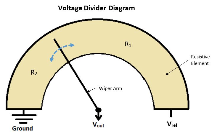
The image above helps illustrate the basic principle behind how a voltage divider works. The resistive element, also called a carbon track, is basically a piece of graphite. Moving the arm across the resistive element effectively alters the resistance on either side of the arm (R1 and R2). Moving the wiper clockwise increases R2 and decreases R1 and moving it counterclockwise does the opposite.
Let's show how the APP sensor works as a voltage divider. When you step on the gas pedal, you move the wiper arm closer to the reference voltage end of the resistive element (Vref). What does this do to the output voltage sent to the ECU? Imagine current flowing from positive (Vref) to the wiper arm. By moving the arm closer to the reference voltage, you decrease the "amount of resistance" through which the current must flow before it reaches the wiper arm. This increases the output voltage to the ECU. The exact relationship between the output voltage, the reference voltage, and the position of the wiper arm can be written as an equation:
Deriving this equation is simple. It involves use of Ohm's law (V=IR) and Kirchoff's Current or Voltage Law. We'll forgo this derivation, as the key here is to understand the concept. The ECU provides a reference voltage to the APP sensor. Physical movement of the pedal moves a wiper across a resistance element and alters the output voltage to the ECU. The ECU takes in this signal, and sends an appropriate signal to a throttle actuator, which moves the throttle plate.
The throttle position sensor works in a similar way. The potentiometer wiper is connected to the butterfly valve spindle. As the butterfly valve opens and closes, it varies the output voltage from 0 to the reference voltage. This output voltage is sent to the ECU. This is how the ECU knows the position of the throttle plate.
The problem with potentiometer-based sensors is that, as the wiper arm and the resistive element rub against one another, they eventually wear out. Newer accelerator pedal position sensors and throttle position sensors don't have this problem, as they use Hall effect as their basic operating principle. These sensors contain transducers that convert external magnetic fields into voltage. Using magnets placed on the pedal and throttle shaft as reference points, Hall effect sensors output a different voltage depending on the intensity of the magnetic field. As the pedal or throttle moves, so does the magnet. This movement changes the magnetic field strength and thus alters output voltage from the sensor to the ECU.
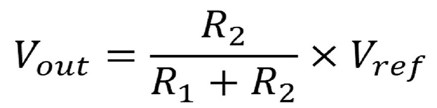
Now let's have a look at how these two sensors interact. Electronic Throttle Control is a closed loop system. The throttle opens based on user input (which is transmitted to the ECU via the accelerator pedal sensor), and adjusts based on readings from the throttle position sensor (which measures the position of the butterfly valve spindle).
.png)
Consider the feedback loop above. If you suddenly stomp on the accelerator, the accelerator pedal position sensor provides the “reference input”- a voltage between 0 and Vref- to the ECU. The reference input indicates where you truly want your throttle to be. The ECU interprets this signal and activates an actuator (a motor), which opens or closes the butterfly valve.
The measured output is the position of the throttle after the actuator's initial movement. This position is transmitted to the computer via the throttle position sensor's output voltage. The discrepancy between where the user wants the throttle (as indicated by the APP sensor) and the throttle's current position (as indicated by the TPS) is the “measured error.” The computer reads this error, and sends an appropriate new signal to the throttle actuator to get the throttle where the driver wants it. The new position is read via the throttle position sensor, and the process continues in a loop.
A major benefit of “Fly by Wire” systems is that it allows for easy integration of systems such as adaptive cruise control, brake override systems, and electronic stability control. Modern Fly by Wire systems include multiple TPSs and APP sensors, and throw a fault code if there is a discrepancy between redundant sensors.
So there you have it. Drive-by-wire systems in their entirety. But i know what you're thinkin; yes that was helpful and all but what the hell is throttle lag and how the hell do i fix it?
Well that's the easy part. To fix throttle lag simply buy a Windbooster Throttle Controller. Problem solved.......
Alright fine i'll explain throttle lag too, here we go; like with most electronic control systems, there is redundancy built into drive-by-wire systems. Instead of just one demand sensor at the pedal, there are two. Same goes with the feedback sensor at the throttle body. This is to avoid loss of control should one fail. The complex nature of this system with its variety of potentiometers, computers, sensors and management systems is what results in a noticeable delay when you first hit the pedal, known as throttle lag or dead zone. No matter how hard or fast you stomp on your accelerator there is no overcoming this delay, it is an inherent electrical delay that physical input cannot conquer.
This is where the Windbooster Throttle Controller comes in.
The WINDBOOSTER throttle controller modifies the voltage signal from the drive-by-wire pedal assembly to allow you to tune the response from your accelerator pedal and greatly reduce the dead zone from when you initially depress the pedal commonly referred to as throttle lag. The WINDBOOSTER is providing new points of reference for the vehicle's throttle mapping. It is still working within the standard parameters; however, it introduces a far sharper throttle curve. It is also bringing the throttle in earlier in the pedal stroke, introducing petrol and air into your engine earlier in the throttle stroke thus improving throttle response and acceleration.
The real benefit of the Windbooster though is its ability to give you complete control over the throttle response of your engine, if your engine is too responsive you can dampen its response to a level that suits your driving style. You can also change the Windboosters settings and modes on the fly so if you are driving along the freeway and need to overtake someone, crank the Windbooster up a few levels to deliver better throttle response, or if you are towing a trailer/ caravan you can bump up the throttle settings to account for the extra added weight. Don't just take our word for it though, every Windbooster comes with a 30-day money back guarantee so you can try the Windbooster and see its effectiveness for yourself.